Exam Topics
- F5CAB2
- F5CAB2.01
- Illustrate the use of a trunk in a BIG-IP solution
- Demonstrate ability to assign VLAN to interface and/or trunk
- Distinguish between tagged vs untagged VLAN
- Compare Interface status (Up/Down)
- Explain the dependencies of interfaces/trunks, VLANs, self-IPs
- F5CAB2.01
Introduction
Before you can use a BIG-IP system to create virtual servers and deliver applications, one of the first and most critical steps is connecting the device to the network.
While this starts with physical interfaces, F5 BIG-IP introduces additional networking concepts beyond simply assigning an IP address to an interface. Concepts such as trunks, VLANs, and Self IPs define how the F5 BIG-IP connects to and communicates with the network.
In this article, we will provide an overview of interfaces, trunks, VLANs, and Self IPs, explaining what each component is, why it exists, and how they interact with one another within the BIG-IP networking model.
Interface in F5 Big-IP
The first and most intuitive networking concept is the interface. An interface represents a network connection on the system. In most cases, this is a physical network port on a hardware appliance. In a virtual BIG-IP system, it may instead be a logical network interface provided by the hypervisor but it will still shows as interface on the F5 Big IP software.
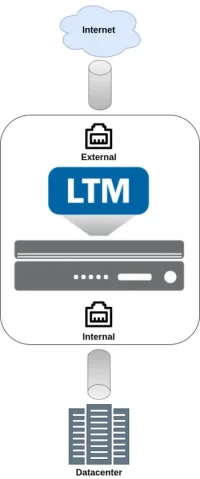
In this example, the F5 BIG-IP is deployed with two interfaces, separating internal and external networks. This design is commonly referred to as a dual-armed deployment.
In practical terms, the interface is where you connect an Ethernet or fiber cable on the appliance. A BIG-IP system can have multiple interfaces, allowing it to serve different purposes, such as connecting to multiple networks, separating traffic types, or supporting various application flows.
Trunk in F5 Big-IP
In the F5 environment, a trunk refers to the aggregation of multiple interfaces into a single logical link. This provides two main advantages.
First, it increases bandwidth capacity by combining multiple interfaces, for example achieving 2 Gbps instead of 1 Gbps. Second, it improves resiliency, since traffic can continue to flow even if one of the member interfaces fails.
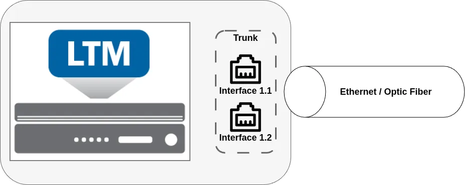
In this example, interfaces 1.1 and 1.2 are bundled together into a single trunk, which operates as one logical object.
VlLAN in F5 Big-IP
A VLAN, as in any standard networking model, defines a logical network segment. It allows multiple logical networks to share the same physical infrastructure while remaining isolated from one another.
This design allows multiple networks to be assigned to the same interface or trunk. Without VLANs, only a single network could exist on an interface or trunk.
Each logical network is represented by a VLAN ID, a numeric identifier typically ranging from 1 to 4094. VLAN IDs ensure proper traffic separation while allowing shared use of the same physical network infrastructure.
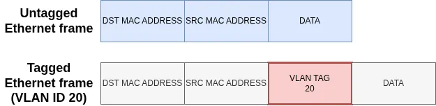
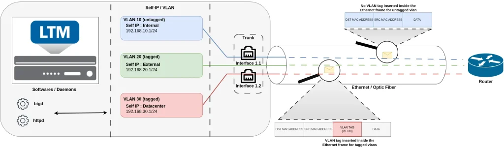
VLANs on an interface or trunk can be tagged or untagged. Tagged VLANs insert a VLAN ID into each Ethernet frame, while only a single untagged VLAN can exist per interface or trunk, carrying traffic without tagging.
While VLANs are optional on many network devices, BIG-IP systems rely heavily on them. On F5 BIG-IP, every network is internally represented by a VLAN, even when no explicit VLAN tagging is required. To assign an IP address via a Self IP (as explained in the following section), you must first create a VLAN, even if it is untagged on the interface or trunk. The VLAN serves as the link between the Self IP and the physical network, ensuring that the IP address can communicate through the assigned interface or trunk.
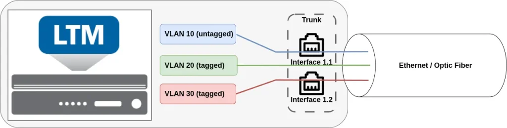
In this example, three VLANs (10, 20, and 30) are created. VLAN 10 is configured as untagged, while VLANs 20 and 30 are tagged. All VLANs are assigned to an interface (or, in this case, a trunk), allowing them to share the same physical infrastructure.
Self IP in F5 Big-IP
A Self IP represents an IP address assigned to a VLAN. It is through a Self IP that the BIG-IP system establishes IP-level connectivity between its software components and the physical network.
Self IPs allow the system itself to send and receive traffic on a VLAN, enabling functions such as routing, health monitoring, management access, and high availability communication. In short, a Self IP is how the BIG-IP becomes a reachable and active participant on a given network.
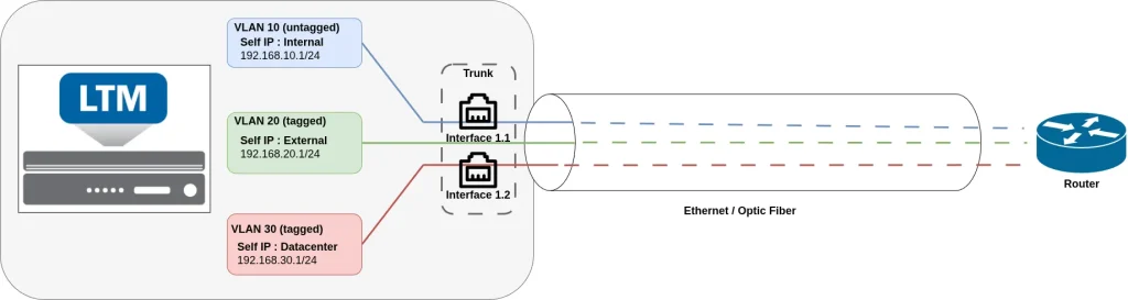
In this example, the Self IP 192.168.10.1/24 is assigned to VLAN 10, the Self IP 192.168.20.1/24 to VLAN 20, and the Self IP 192.168.30.1/24 to VLAN 30. Because VLANs are bound to an interface or trunk, the Self IPs are indirectly associated with the interface or trunk through their respective VLANs.
As a result, any traffic that uses a specific Self IP is confined to its corresponding VLAN and remains isolated from other VLANs.
Relationship Between Interfaces, Trunks, VLANs, and Self IPs
Looking at the big picture, BIG-IP networking is organized in a layered and hierarchical model :
- To connect to the network, the BIG-IP system uses interfaces as the underlying physical or logical network ports. These interfaces can be bundled together into a trunk to increase bandwidth and provide redundancy.
- Once interfaces or trunks are defined, VLANs are assigned to them, either as tagged or untagged VLANs. VLANs define the logical networks that the BIG-IP will participate in.
- Finally, Self IPs are created and assigned to VLANs. These Self IPs provide the BIG-IP with IP-level connectivity on each network.
Together, interfaces provide connectivity, trunks add resiliency and capacity, VLANs define network segmentation, and Self IPs allow the BIG-IP system to communicate on each network.
Configure network using Configuration Utility (GUI)
Now that we have seen how interfaces, trunks, VLANs, and Self IPs are organized, let’s look at how to configure and verify each of these components using the Configuration utility.
Interface
Interfaces can be accessed from the menu: Network → Interface.
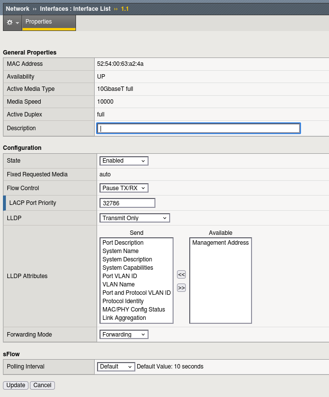
The primary configuration option for an interface is its state:
- Availability: Displays the current operational state of the interface.
- State: Allows you to administratively enable or disable the interface.
This menu also provides additional information and configuration options, including:
- The MAC Address in use
- The actual speed
- LACP (Link Aggregation Control Protocol) settings
- LLDP (Link Layer Discovery Protocol), which is enabled for transmission by default
- Traffic flow options, allowing fine-grained control over interface behavior
Trunk
Trunk can be configured from the menu Network → trunks
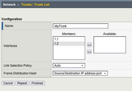
In the trunk menu, it display the available interface that can be used for a trunk. Move the interface from the available to the member section to add interface to the trunk.
You can also specify some LACP options.
Vlan
VLANs are configured from the menu: Network → VLAN.
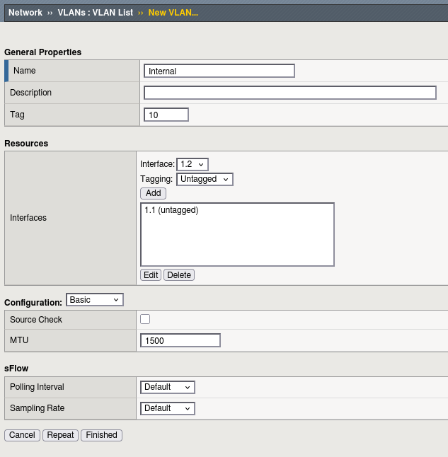
From this menu, you can:
- Customize the VLAN ID
- Bind the VLAN to an interface or trunk
As explained earlier, VLANs can be tagged or untagged, but remember that only one untagged VLAN can be assigned per interface or trunk.
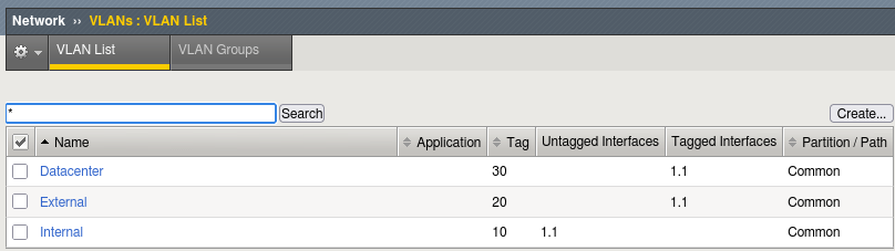
The VLAN list menu also provides a summary view of each VLAN, showing:
- The interfaces or trunks to which it is assigned
- Whether it is configured as tagged or untagged
This centralized view makes it easy to manage VLAN assignments and verify it.
Self IP
Self IPs are configured from the menu: Network → Self IP.
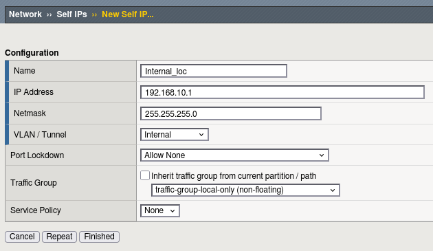
This is where you assign an IP address to a specific VLAN, enabling the BIG-IP system to communicate on that network.
You can also configure Port Lockdown settings for each Self IP from this menu, controlling which ports are open for traffic.
A key concept to understand is the Traffic Group. The traffic group determines whether a Self IP is floating (shared between devices in a high availability setup) or non-floating (tied to a single device). This setting is essential for proper high availability and failover behavior.
Configuration of network profiles using tmsh (CLI)
It is always a good practice to understand how to modify the configuration using tmsh, as tmsh remains accessible through the console. This is especially important when working with network parameters, which may need to be corrected or restored using console (CLI) access if connectivity is lost.
Interface
All network-related commands in BIG-IP are located under the net command space.
To configure an interface (note that you cannot create a new interface, only modify existing ones), use the modify command:
modify net interface
For example, to administratively disable interface 1.1, run:
modify net interface 1.1 disabled
To display the current status and statistics of an interface, use the show command:
show net interface 1.1
Example output :
-------------------------------------------------------------
Net::Interface
Name Status Bits In Bits Out Pkts In Pkts Out Drops Errs Media
-------------------------------------------------------------
1.1 disabled 173.6K 36.0K 406 60 0 0 none
The output provides:
-
Status – whether the interface is enabled or disabled
-
Traffic statistics – bits and packets transmitted and received
-
Drops and errors – packets dropped or errors related to the media
This information is useful for verifying interface state, monitoring traffic, and troubleshooting connectivity issues.
Trunk
To create trunk, use the following command :
create /net trunk trunk_name interfaces add { interface_names }
To display the trunk use the show command :
show /net trunk my_trunk
--------------------------------------------------------------------
Net::Trunk
Name      Status  Bandw  Bits  Bits  Errs  Errs  Drops  Drops  Colli
                   Mbps    In   Out    In   Out     In    Out  sions
--------------------------------------------------------------------
my_trunk      up   2000  7.1G  5.1K     0     0   6.8M      0      0
The show command display the network statistics. To get the detail of the created trunk, use list instead :
list /net trunk my_trunk
net trunk my_trunk {
    cfg-mbr-count 2
    id 1
    interfaces {
        1.1
        1.2
    }
    lacp enabled
    mac-address 00:01:d7:92:9d:54
}
While show give statistics, the list command display which interfaces are part of the trunk.
VLAN
To create a new VLAN, use the create command :
create net vlan <VLAN-Name> tag vlan-id interfaces add { interface-name { tagged | untagged } }
Here in this example, we create the vlan “vlan50” with a VLAN-Id of 50 on the interface 1.1. The vlan is tagged :
create net vlan vlan50 tag 50 interfaces add { 1.1 { tagged } }
As any object, you can perform a modification using the modify command. For example modify the vlan tag of an already configured vlan :
modify net vlan vlan50 tag 150
You can now verify the vlan using the show command :
show net vlan <VLAN-Name>
Here is an example for the vlan50 previously created :
-------------------------------------
Net::Vlan: vlan50
-------------------------------------
Interface Name      vlan50
Mac Address (True)  52:54:00:63:a2:4a
MTU                 1500
Tag                 50
Customer-Tag

  | Incoming Discard Packets          0
  | Incoming Error Packets            0
  | Incoming Unknown Proto Packets    0
  | Outgoing Discard Packets          0
  | Outgoing Error Packets            0
  | HC Incoming Octets              360
  | HC Incoming Unicast Packets       0
  | HC Incoming Multicast Packets     4
  | HC Incoming Broadcast Packets     0
  | HC Outgoing Octets              790
  | HC Outgoing Unicast Packets       0
  | HC Outgoing Multicast Packets     9
  | HC Outgoing Broadcast Packets     0
  | PVA Incoming Packets              0
  | PVA Incoming Octets               0
  | PVA Outgoing Packets              0
  | PVA Outgoing Octets               0

  -----------------------
  | Net::Vlan-Member: 1.1
  -----------------------
  | Tagged    yes
  | Tag-Mode  none

     ---------------------------------------------------------------
     | Net::Interface
     | Name    Status    Bits   Bits  Pkts  Pkts  Drops  Errs  Media
     |                     In    Out    In   Out
     ---------------------------------------------------------------
     | 1.1   disabled  173.6K  36.0K   406    60      0     0   none
Notice that the show command display if the vlan is tagged or untagged. It also display the subsequant interface used and it’s status (in this case the interface is disabled !).
Self-IP
To configure the self IP use the create command :
create net self internalSelf address 192.168.50.1/24 vlan vlan50
To display the Self IP configuration, use the list command :
list net self internalSelf
net self internalSelf {
address 192.168.50.1/24
traffic-group traffic-group-local-only
vlan vlan50
}
The show command will display the hierarchy of profile, but not the IP address/VLAN assigned to the self IP :
show net self Internal_loc

--------------------------
Net::Self IP: Internal_loc
--------------------------

---------------------------------------
| Net::Vlan: Internal
---------------------------------------
| Interface Name Internal
| Mac Address (True) 52:54:00:63:a2:4a
| MTU 1500
| Tag 10
| Customer-Tag

-----------------------
| Net::Vlan-Member: 1.1
-----------------------
| Tagged no
| Tag-Mode none

---------------------------------------------------------------
| Net::Interface
| Name Status Bits Bits Pkts Pkts Drops Errs Media
| In Out In Out
---------------------------------------------------------------
| 1.1 disabled 173.6K 36.0K 406 60 0 0 none
Conclusion
BIG-IP networking follows a clear, layered architecture:
-
Interfaces provide the physical or logical network connectivity
-
Trunks aggregate interfaces to increase bandwidth and provide redundancy
-
VLANs define logical networks and are assigned to interfaces or trunks
-
VLANs can be tagged or untagged
-
Only one untagged VLAN is allowed per interface or trunk
-
-
Self IPs provide IP-level connectivity and are always associated with a VLAN
-
Self IPs can be floating or non-floating, based on the traffic group
-
Understanding how these components fit together is essential for properly designing, configuring, and troubleshooting BIG-IP network connectivity.